Sidebar
dev:crosscompiler:cfg
Control Flow Graph
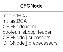
The Control Flow Graph is an intermediate form where the instructions and the control flow are shown as a directed graph. It enables certain optimizations. For each method of a class an own CFG is built. Nodes in such a CFG represent a sequence of instructions with no branches. Further, there must be no branch target within a node. Branches in a method are represented by directed edges which connect the nodes. Each node has n predecessors and m successors as well as an index to the address of the first and the last Bytecode instruktion of this node.
In order to build the CFG of a method, unconditional and conditional jumps or branches have to be found.
Implementation
At the beginning the whole code of a method is a single node. Now the first branch is searched. This could be instructions such as if_xx, goto, goto_w, tableswitch and lookupswitch. Calls to methods do not change the flow of the program and don't give edges. The same is true for subroutines with jsr and ret. For searching this branch instructions all Bytecode instructions are stored in a lookup table together with attributes. These attributes indicate for example whether they are branch instructions. Special care has to be taken for instructions whithout a fixed length, among them are wide, tableswitch and lookupswitch.
As soon as a branch instruction is found, the node is split. The node which contains the branch target must be split as well.
Splitting at Branch Instruction
- Split after branch. New node is successor of the actual node if conditional branch (if_xx). If unconditional branch → do not add to successors.
- If branch instruction is last instruction of a node → no splitting.
Splitting at Branch Target
- If branch target is first instruction of a node → no splitting.
- New node is successor of node with the original branch instruction.
- If target instruction is goto: That means the target node of the branch consists of an unconditional branch. We can therefore omit this node and directly enter the node, which is the target of this unconditional branch, as a successor of the actual node.
Handling of Exceptions
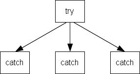
Methods with catch clauses must be handled with special care. Nodes, which represent catch clauses must be determined with the help of the exception table. Further, these nodes must be added as predecessors to their corresponding try-nodes. Such nodes are marked with the field isCatch.
Loop Headers
As a next step, all nodes are traversed and the loop headers marked. This information is later needed for the SSA.
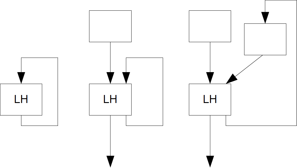
Starting from the root node the graph is recursively traversed. For each node with the flag visited already set, the field nofBackwardBranches will be incremented. Every node with nofBackwardBranches > 0 is a loop header. The following figure depicts a couple of cases.
Dead Code Elimination
If a node has a single goto instruction, this node can be eliminated. switch statements often lead to such nodes. For this the branch, which leads to this special node, must be corrected in way that its target directly points to the node with the target of the goto. Important: The original Bytecode is not changed in any way. In there the target address of a switch table still contain the dead nodes. Later on, we no longer parse the Bytecode and determine addresses but simply follow the successors of a node. The successors must be entered in the same order as the original branch targets in the Bytecode. For this purpose it's also important to list successors with the same target node multiple times if necessary. To find dead nodes, the flag visited, which was already used for the loop headers, can be reused.
Predecessors
For all nodes its predecessor can be added. For the case that several successors of a node point to the same target node, only one predecessor must be entered.
Dominator
Finally the dominator of each node has to be determined. The resulting structure is called dominator tree and is a n-fold tree, since every node has exactly one reference to another node (its dominator). The dominator tree is used when generating the SSA.
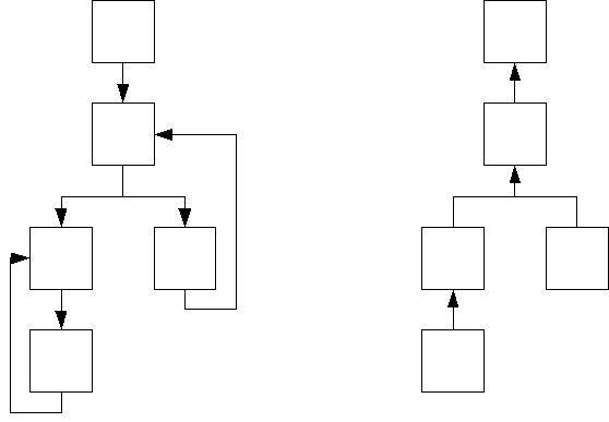
Special care must be given to the case where the root node already has one or more predecessors.
dev/crosscompiler/cfg.txt · Last modified: 2020/06/18 21:29 by ursgraf
Page Tools
Except where otherwise noted, content on this wiki is licensed under the following license: CC Attribution-Share Alike 4.0 International
